Exam 2 review #
Sequential circuit small design #
- All small and large sequential circuits are made of flip flops and sets of combination circuits
- Contrary to CC (combination circuits), a sequential circuit design has states and transitions from a current state to the next state
- A sequential circuit design problem is typically modeled as a finite state diagram
- FSD consists of circles as states and arcs (arrows) as transitions, which specifies the behavior of a sequential circuit
- FSD is systematically converted into circuit called finite state machine
- Finite state machines designs categorized into Mealy, Moore, or hybrid
- Mealy is a FSM whose output values are determined by its current e state and input.
- Moore machine whose output values are determined solely by its current inputs.
Moore machines
- Output depends only upon present state
- If input changes output does not change
- More number of states required
- There is more hardware requirement
- React slower to inputs (one clock cycle later)
- Synchronous output and state generation
- Output is placed on states
- Easy to design
Mealy machine
- Output depends on present state as well as present input
- If input changes, output also changes
- Less number of states
- Less hardware
- React faster to inputs
- Asynchronous output generation
- Output is placed on transitions
- Difficult to design
Reviewing the design process of a sequential circuit #
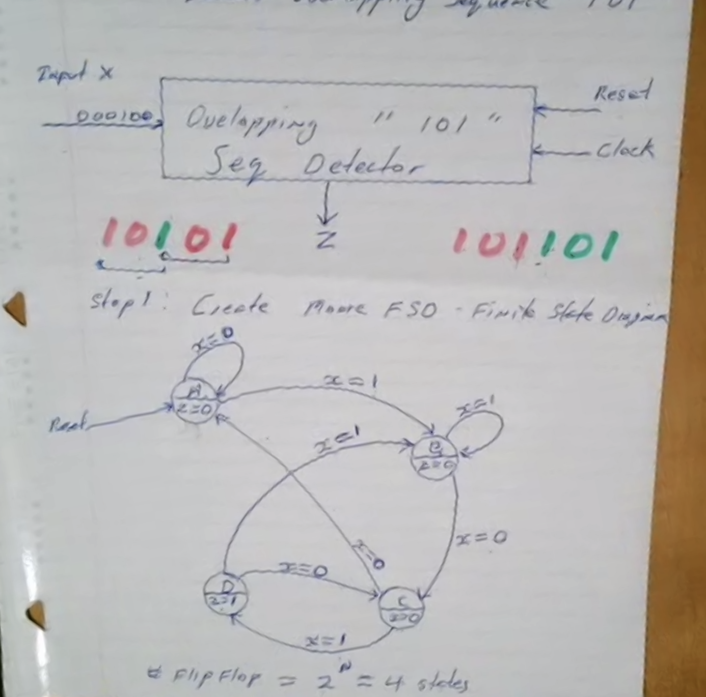
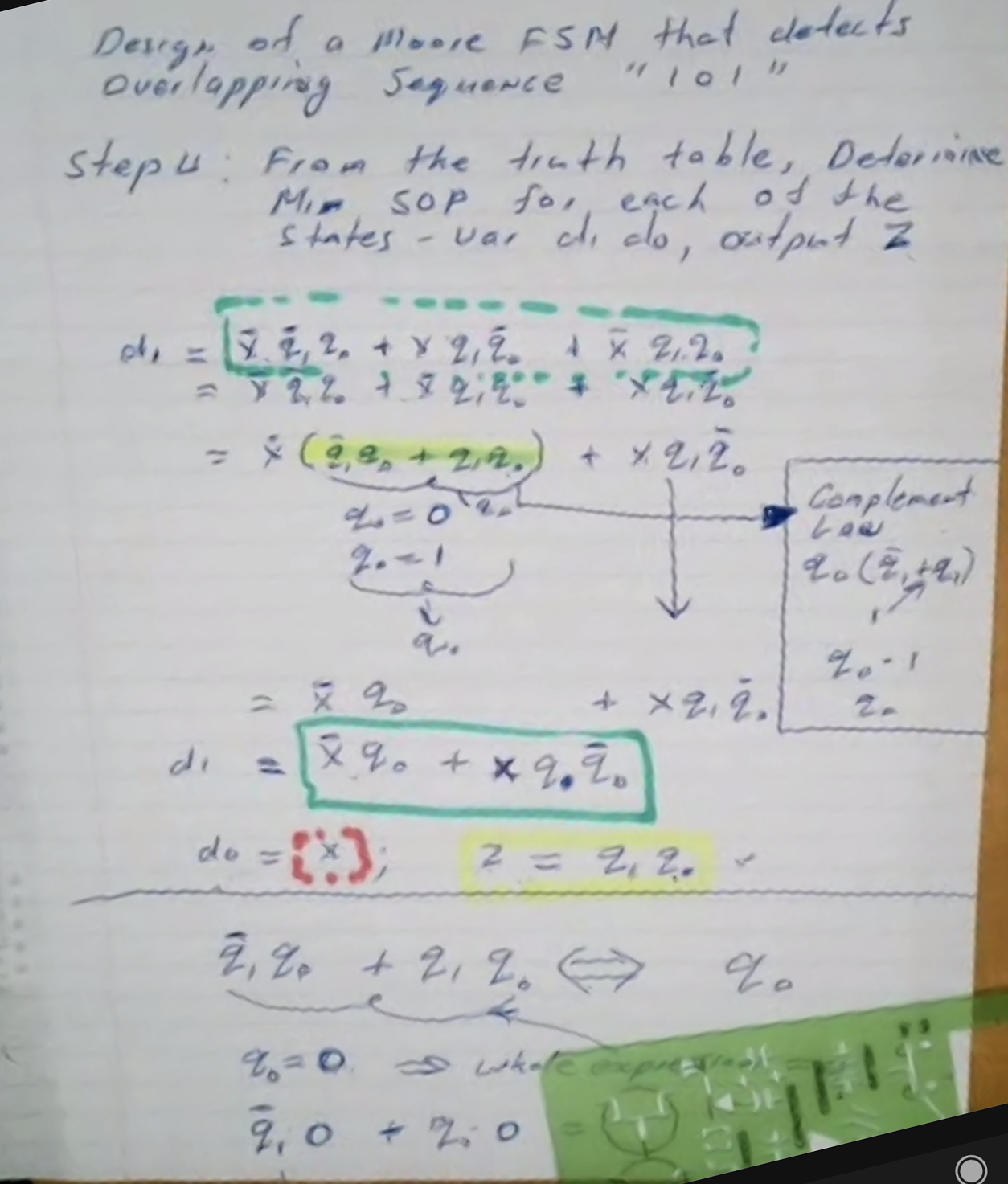
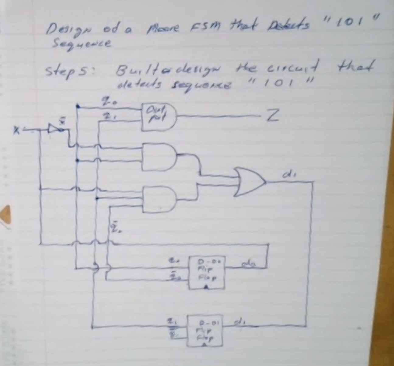
Example: design of a Moore FSM that detects overlapping sequence “101”.
Step 1: design the FSD
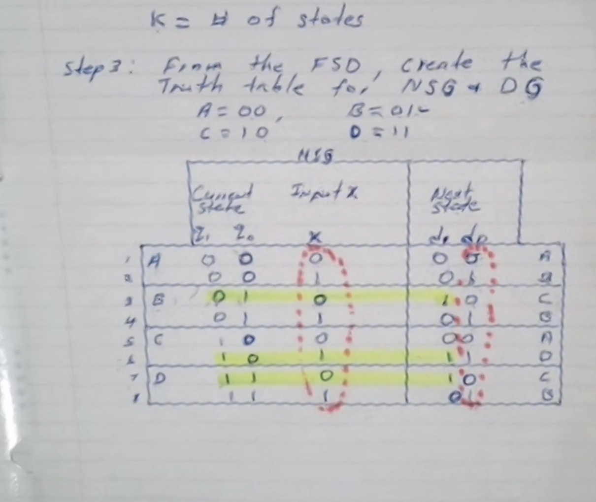
Step 2: Determine the minimum number of bits required to store the states
\( \text{number of bits } = \log_2 \lceil k \rceil \) , where \( k = \text{ number of states} \)
So we need 2 flip flops to represent the states because \( \log_2 \lceil 4 \rceil = 2 \)
Step 3: From the FSD, create the truth table for the next state generator (NSG) and the output generator (OG)
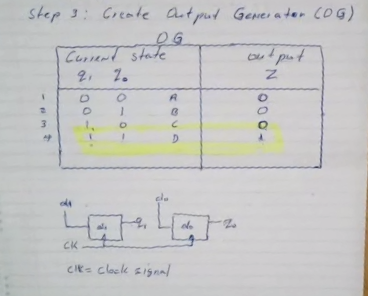
Step 5: built the circuit
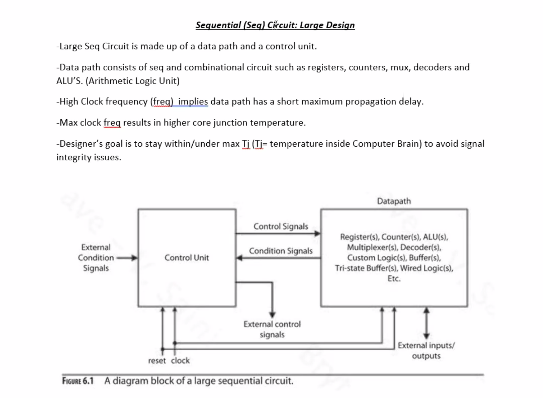
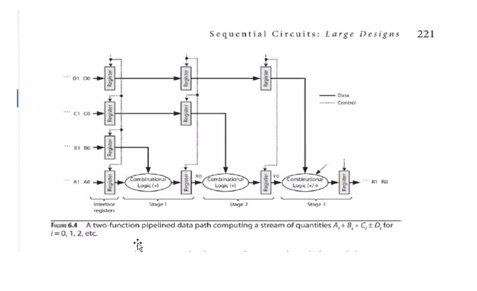
Large design review #