Finite state machine design cont. #
Moore machine design cont. #
Recall
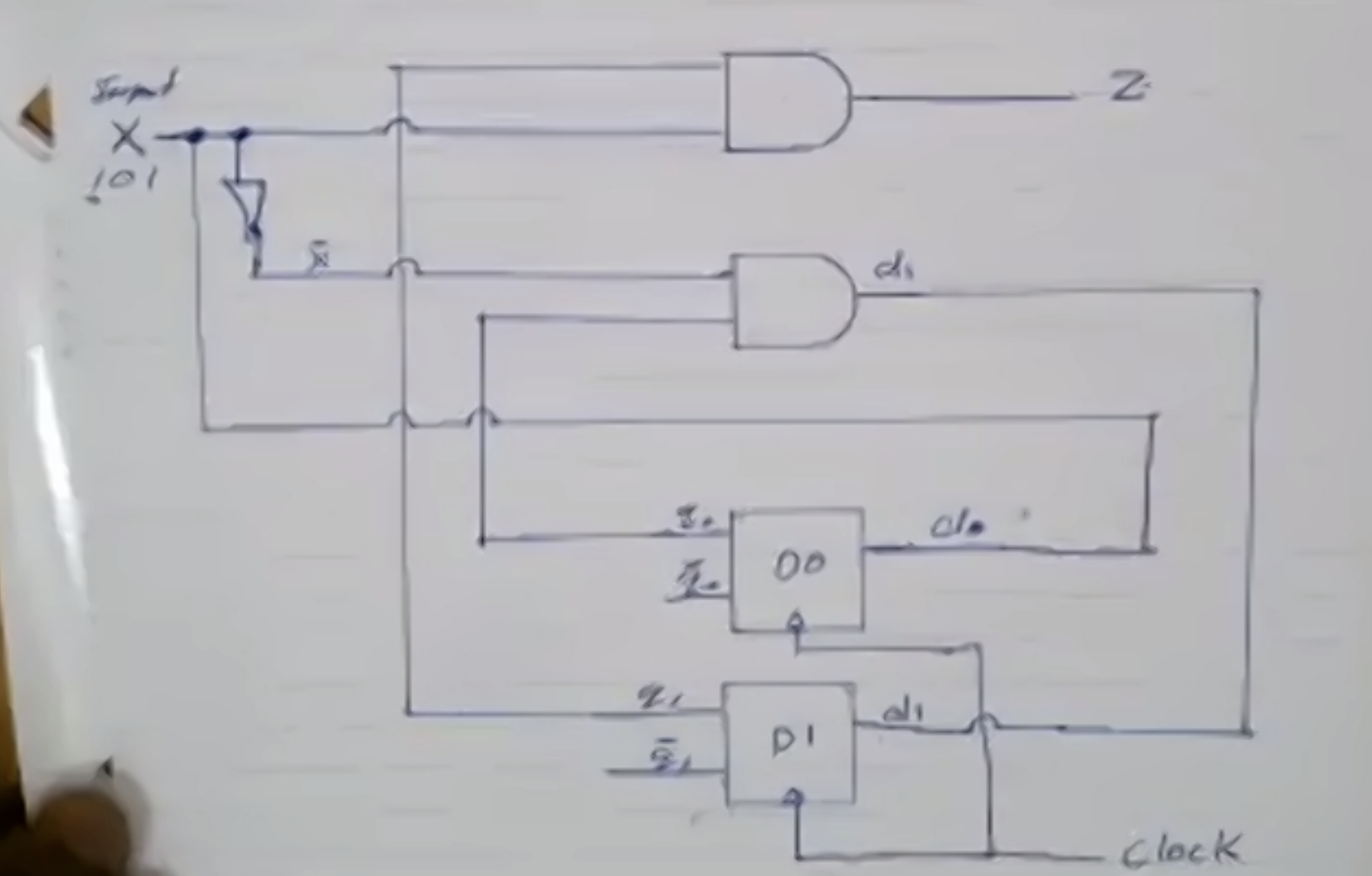
\[\begin{aligned} d_0 &= x \\ d_1 &= \overline{x} q_0 + x q_1 \overline{q_0} \\ Z &= q_0 q_1 \end{aligned}\]Step 5: Circuit diagram
Mealy machine design #
- Output depends on present state as well as present input
- If input changes, output also changes
- Less number of states are required
- There is less hardware requirements
- They react faster to inputs
- Asynchronous output generation
- Output is placed on transitions
- It is difficult to design
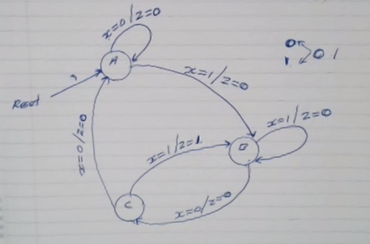
We will design a Mealy machine that detects the same overlapping “101”.
Step 1: Generate the FSD (finite state diagram) for the machine
Step 2: Determine the number of bits needed to store the states
\( \text{number of bits } = \lceil \log_2(k) \rceil = \lceil \log_2(3) \rceil = 2 \) , where \( k = \text{ number of states} \)
Step 3: From FSD, create the truth table where
\( A = 00 \\ B = 01 \\ C = 10 \\ D = 11\)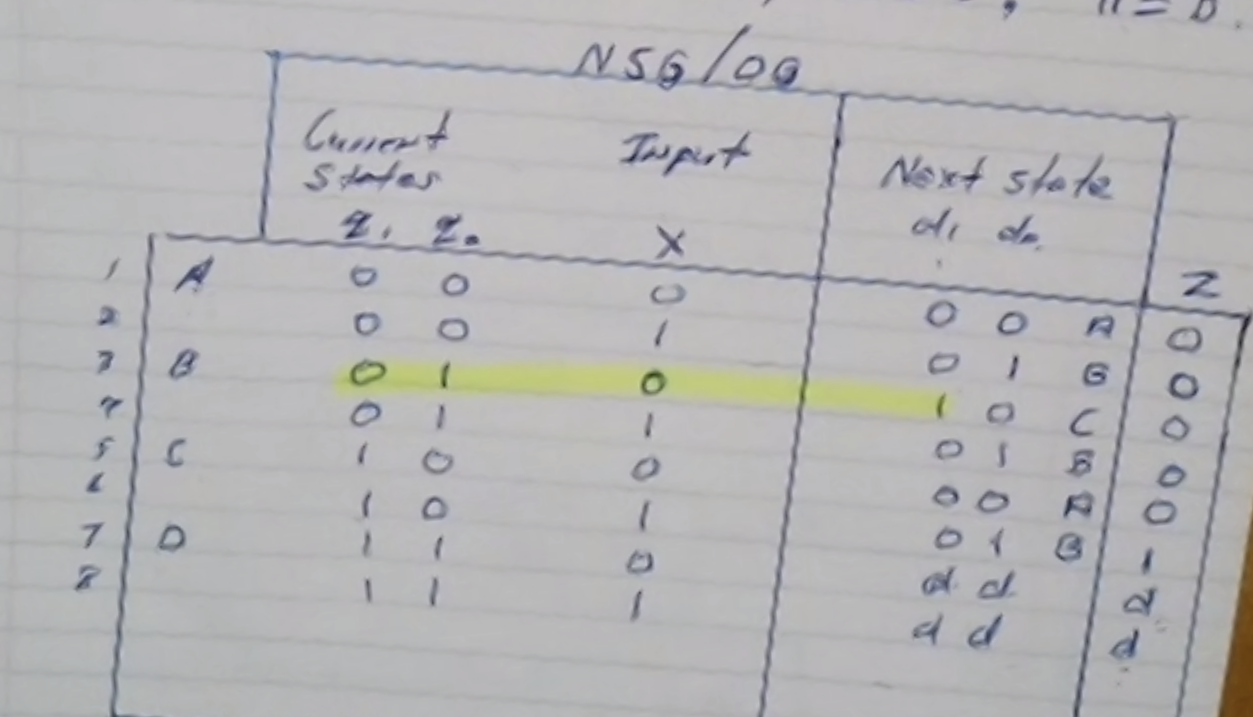
Note: State \(D\) is composed of “don’t cares.”
Step 4: Determine the logical expressions
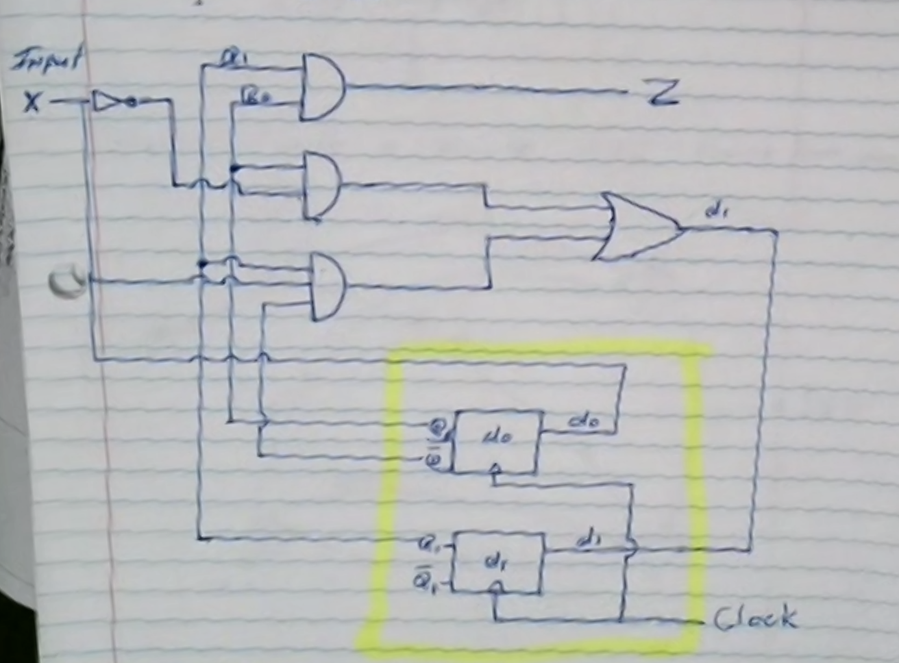
\[\begin{aligned} d_0 &= x \\ d_1 &= q_0 \bar{x} \\ z &= q_1 x \end{aligned}\]Step 5: Draw the circuit diagram