Sequential circuits, large design cont. #
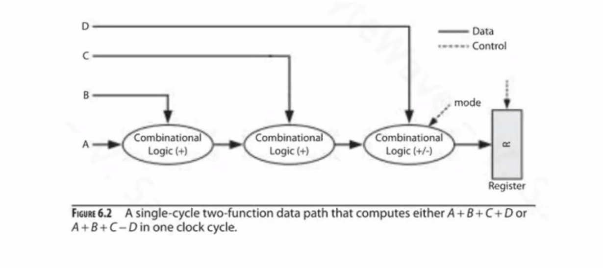
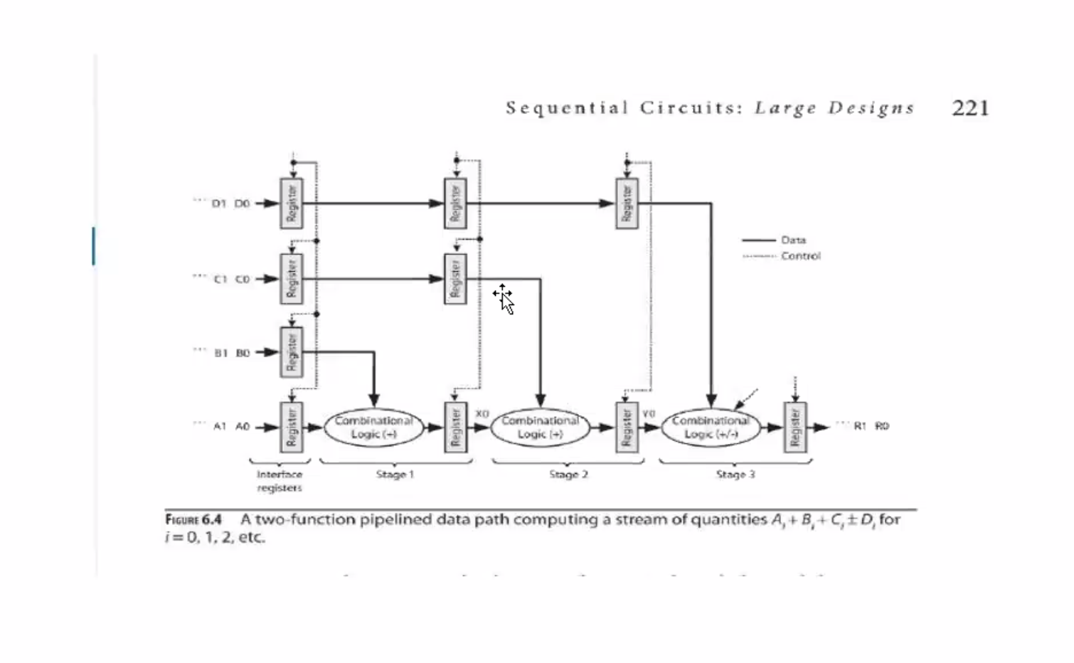
- Data path contains two adder modules and one adder/subtractor module
- The single mode controls the functions of the adder/subtractor modules
-
Data path that computes either of these: \[\begin{aligned} &A + B + C + D \\ &A + B + C - D \end{aligned}\]
-
Equation that estimates the minimum clock period ( \( \tau \) ) required to run the data path
-
\( \text{add} \) stands for adder, \( \text{sub} \) stands for subtractor
-
\( \Delta \) is the time delay from input to output
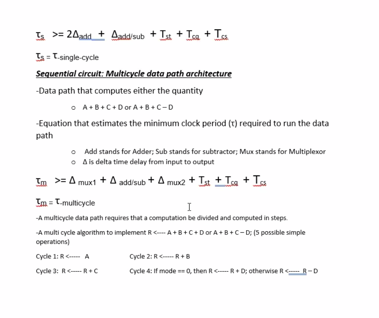
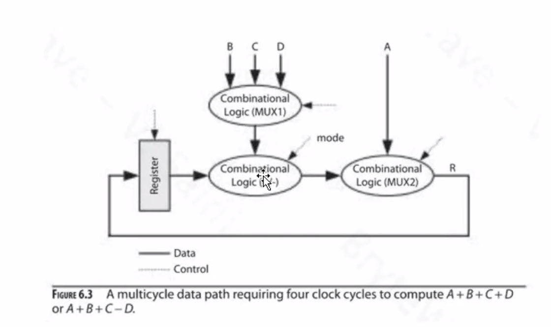
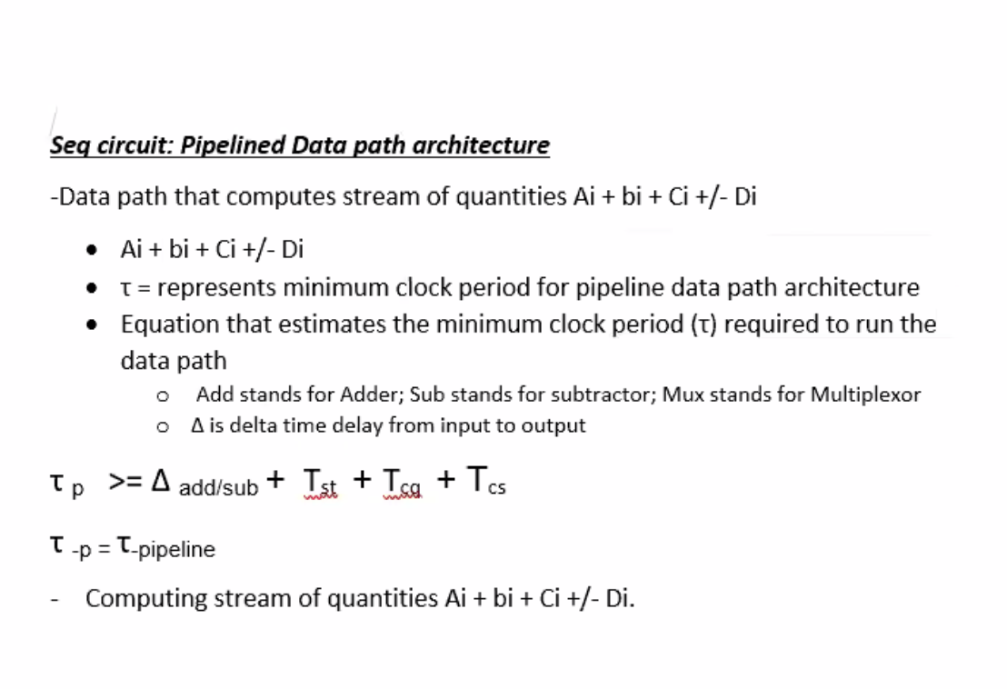
\( \tau_p \geq \Delta_{\text{add/sub} } + T_{\text{st} } + T_{\text{cq} } + T_{\text{cs} }\\\) \( \tau_{p} = \tau_{ \text{pipeline} } \)
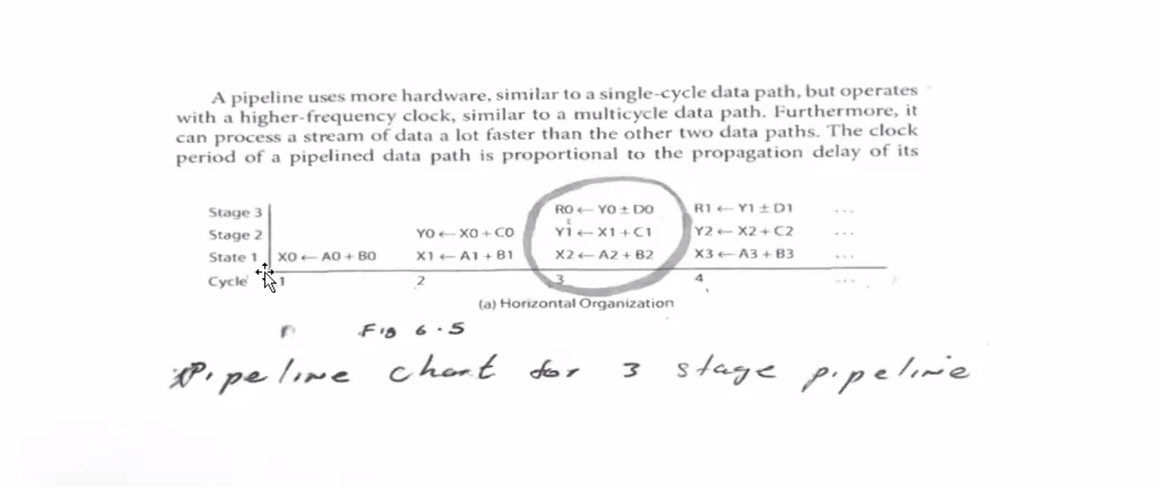
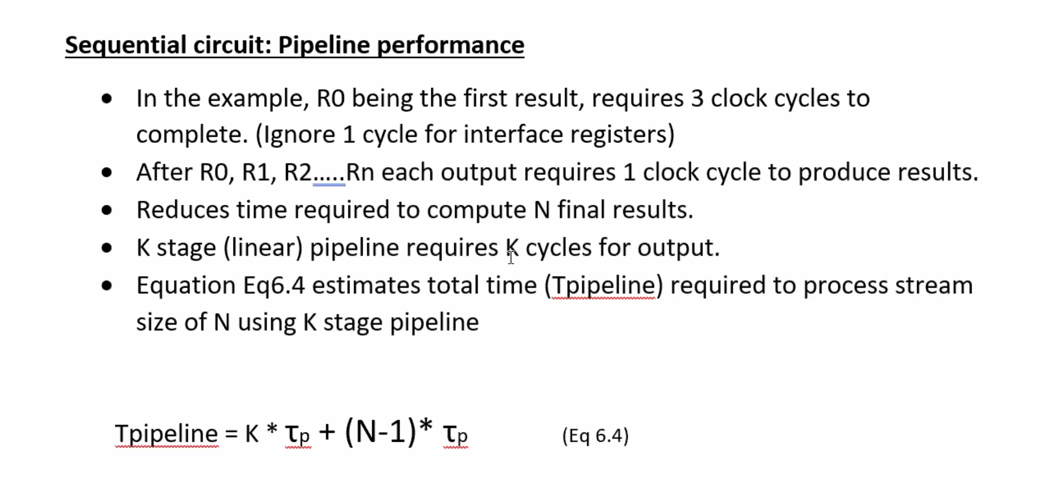
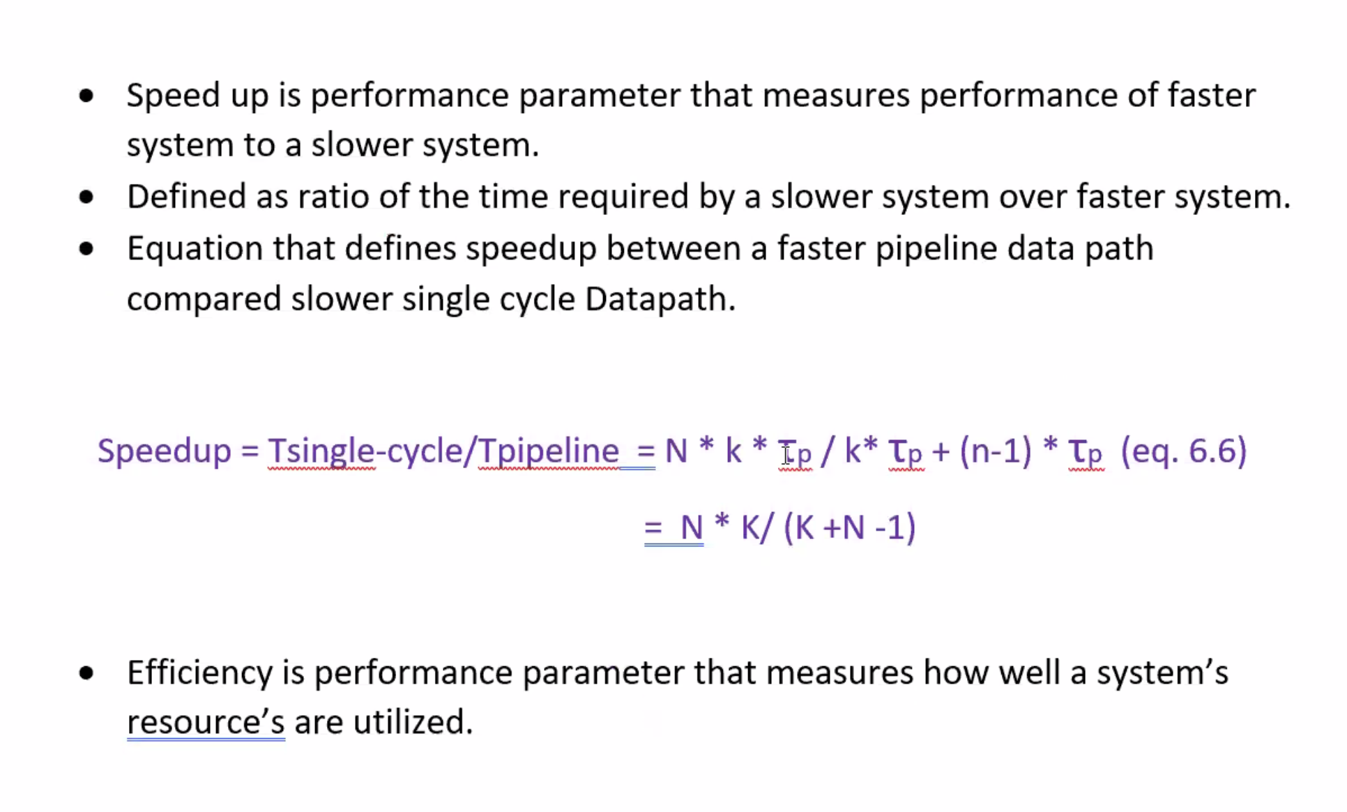
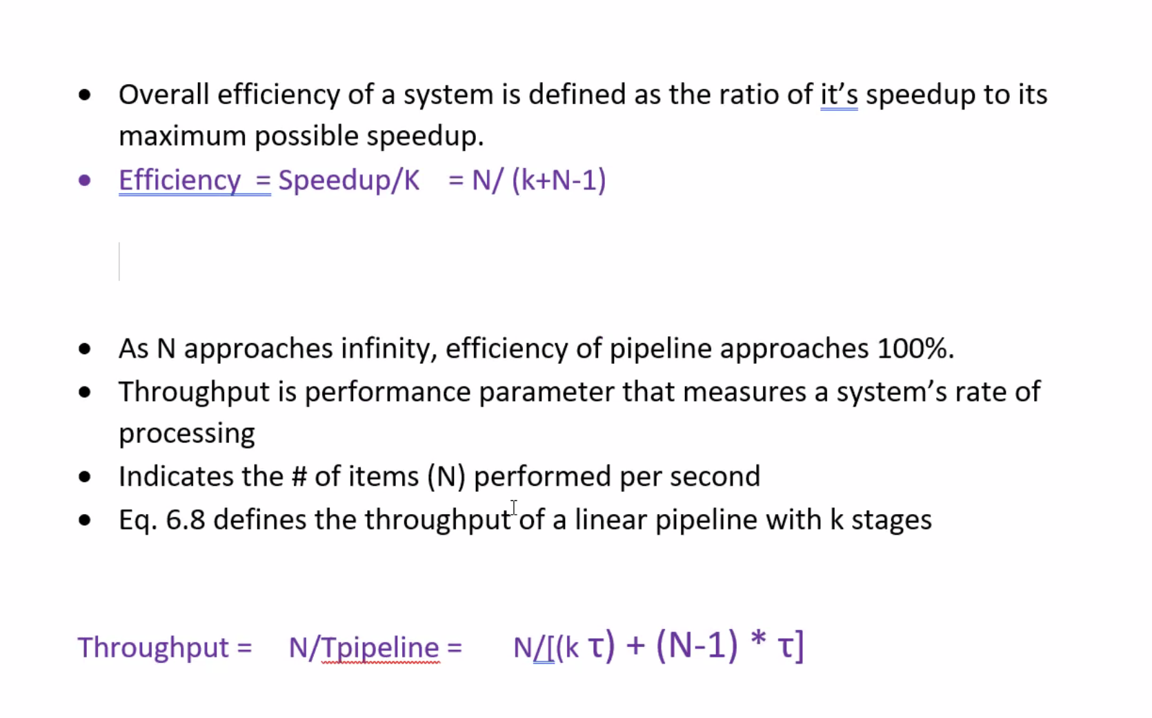
Speedup equation defines the speed up between a faster system and a slower system.