Multiplexers #
An everyday example of a multiplexer is a TV remote.
- Selecting of data or information is a critical function in a digital system and computers.
- A multiplexer (mux for short) is a digital switch. Mux is a circuit used to select and route any of the several inputs to an output signal.
- Mux is a combination circuit, it has the following:
- \( 2^n \) inputs
- \( n \) control inputs, selector signals
- one set of output
- For a mux, the value of the control inputs (selector signal) determines the data input that is selected.
- Multiplexer means many into one. A simple example of a non-electronic circuit of a mux is a single pole multiposition switch. Multi-position switches are widely used in many electronics circuit, however, circuits that operate at high speed require the multiplexer to be automatically selected. A mechanical switch cannot perform this task satisfactorily. Therefore, a mux is used to perform high speed switching and are constructed for digital circuits.
Example
X and Y are inputs, S is the selector signal, r is the output.
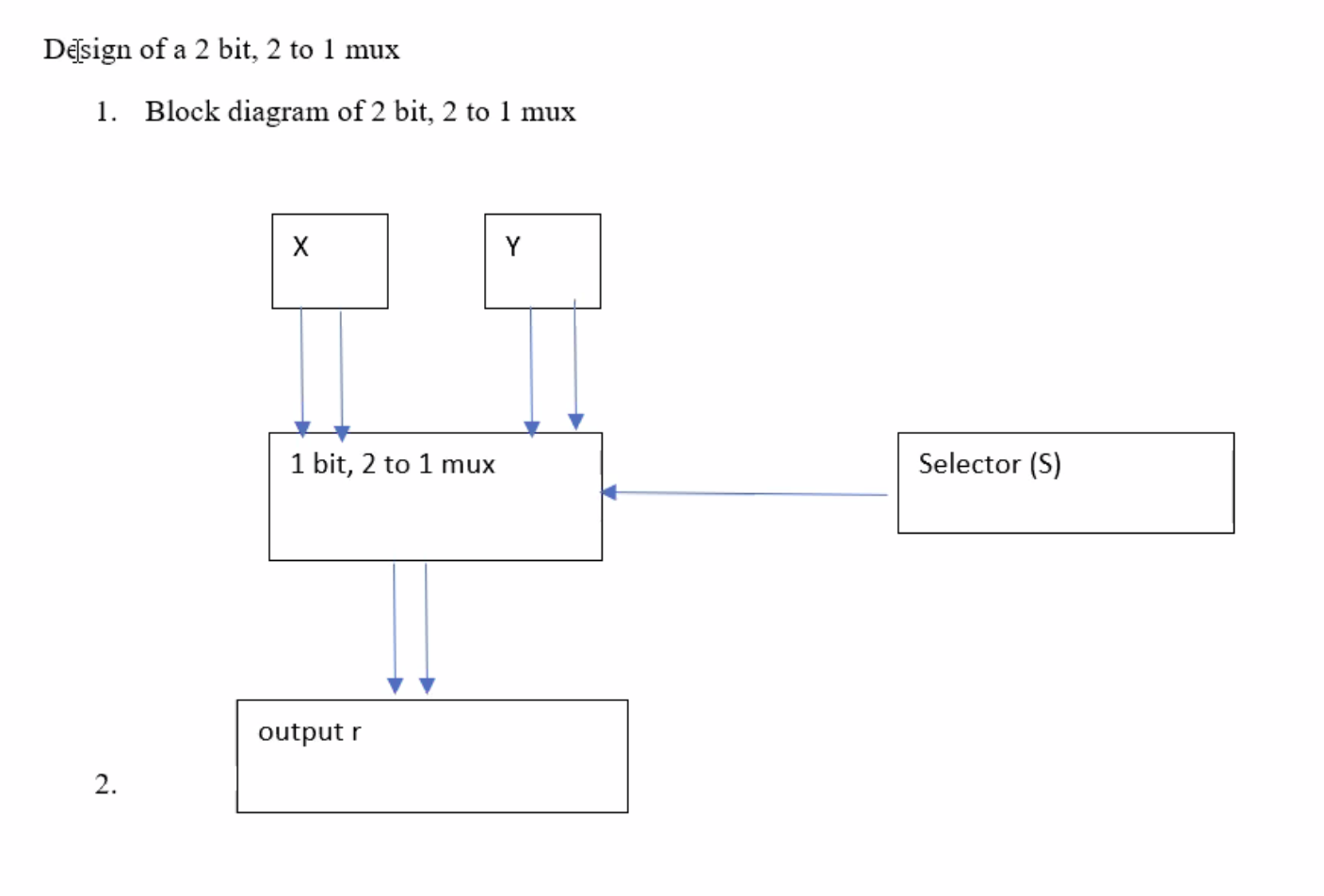
2 to 1 means that it has a total of 2 inputs, with 1 output.
If you called this a “1 bit mux”, then each X and Y would only have one input (0 or 1).
Lets make a truth table of this:
| Selector | Input | Input | Output |
|---|---|---|---|
S |
X |
Y |
r |
| 0 | 0 | 0 | 0 |
| 0 | 0 | 1 | 1 |
| 0 | 1 | 0 | 0 |
| 0 | 1 | 1 | 1 |
| 1 | 0 | 0 | 0 |
| 1 | 0 | 1 | 0 |
| 1 | 1 | 0 | 1 |
| 1 | 1 | 1 | 1 |
So this is our equation we can simplify:
\[\begin{aligned} r = \bar{s} \bar{x} y + \bar{s} x y + s x \bar{y} + s x y \end{aligned}\]Simplifying using a K-map:
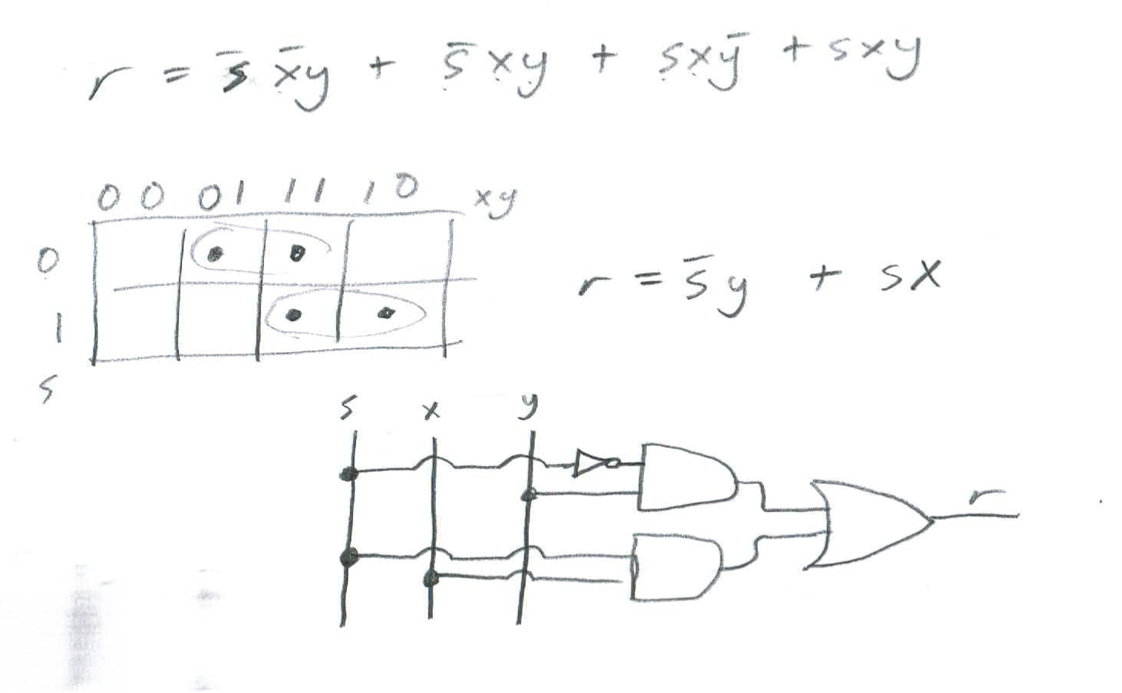
So, the outputs are selected based on the selector signal.
Outputs, Y when S = 0; X when S = 1.